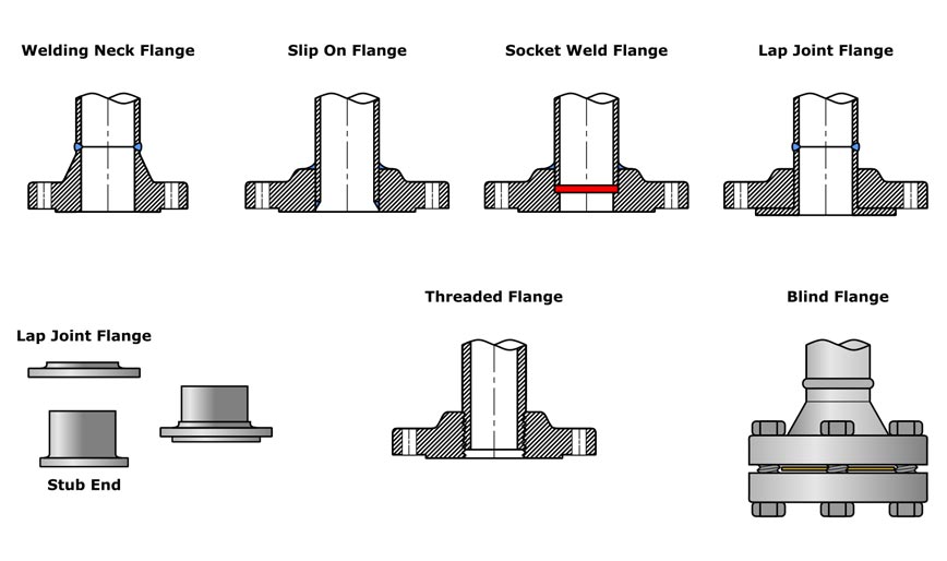
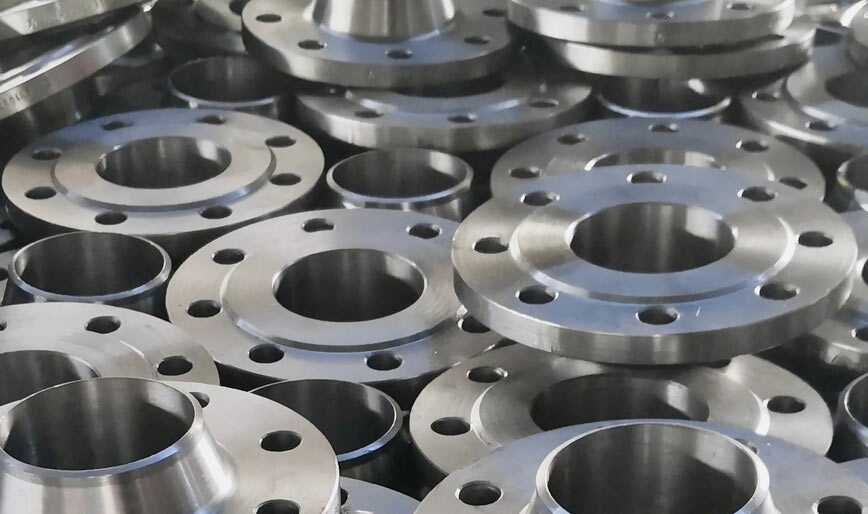
Our range of industrial flanges are ideal for application in diverse industry for high pressure and temperature applications. These flanges are designed with precision for easy installation. Apart from standard flanges, we also offer custom designed flanges to meet the specific application requirements of the customers.
Flanges
|
Stainless Steel
|
ASTM A479, A182 -202,303,304, 304L, 304H, 316, 316L, 316Ti,309, 310, 310S, 321, 321H, 317, 347, 347H, 904L |
|---|---|
|
Duplex & Super Duplex
|
F 44, F 45, F51, F 53, F 55, F 60, F 61 |
|
Carbon Steel
|
ASTM A105, A350 LF2, A106 Gr A, B, C, A333 Gr 6, 3 |
|
Alloy Steel
|
ASTM A182 F5, F9, F11, F12, F21, F22, F91, A335 Gr P1, P11, P12, P5, P9 |
|
Nickel Alloys
|
Nickel 200 (UNS No. N02200), Nickel 201 (UNS No. N02201), Monel 400 (UNS No. N04400), Monel 500 (UNS No. N05500), Inconel 800 (UNS No. N08800), Inconel 825 (UNS No. N08825), Inconel 600 (UNS No. N06600), Inconel 625 (UNS No. N06625), Inconel 601 (UNS No. N06601), Hastelloy C 276 (UNS No. N10276), Alloy 20 (UNS No. N08020) |
|
Copper Alloy Steel
|
C 70600 (Cu-Ni 90/10), C 71500 (Cu-Ni 70/30), UNS No. C 10100, 10200, 10300, 10800, 12000, 12200 |
Weld Neck Flanges
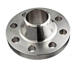
Weld Neck Flange is flanges that designed to be joined to a piping system by butt welding. This kind of flange include lots of specification. Weld Neck Flange is expensive because of its long neck and cost of people for contact WN flange with pipeline or fitting but is preferred for high-stress applications.
| Dimensions: | ANSI B16.5, ANSI B16.47 Series A & B, MSS SP44, ASA, API-605, AWWA, Custom Drawings |
| Size: | 1/2″ (15 NB) to 48″ (1200NB) |
| Class: | 150 LBS, 300 LBS, 600 LBS, 900 LBS, 1500 LBS, 2500 LBS |
| BS: | BS4504 , BS4504, BS1560, BS10 , PN6 , PN10 , PN16 , PN25 , PN40, etc |
| Table: | D / E / F / H / J / K |
| Api Standards: | PSI-2000/3000/5000/10000/etc |
| JIS Standards: | 2220-2004 5k/10k/16k, etc |
| Flange Face Type: | Flate Face (FF), Raised Face (RF), Ring Type Joint (RTJ) |
Long Weld Neck Flanges
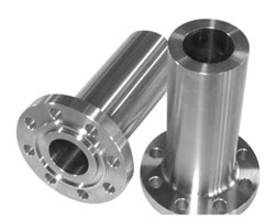
Weld Neck Flanges in hard-to-nd metals. Long Weld Neck Flanges have a hub that extends from the Flanges at the surface, which helps in accommodating the pipe more easily. Alloy Steel Long Weld Neck Flange fall under the group of specialty flanges, reinforcement in services at higher temperatures in the oil industry.
| Dimensions: | ANSI B16.5, ANSI B16.47 Series A & B, MSS SP44, ASA, API-605, AWWA, Custom Drawings |
| Size: | 1/2″ (15 NB) to 48″ (1200NB) |
| Class: | 150 LBS, 300 LBS, 600 LBS, 900 LBS, 1500 LBS, 2500 LBS |
| BS: | BS4504 , BS4504, BS1560, BS10 , PN6 , PN10 , PN16 , PN25 , PN40, etc |
| Table: | D / E / F / H / J / K |
| Api Standards: | PSI-2000/3000/5000/10000/etc |
| JIS Standards: | 2220-2004 5k/10k/16k, etc |
| Flange Face Type: | Flate Face (FF), Raised Face (RF), Ring Type Joint (RTJ) |
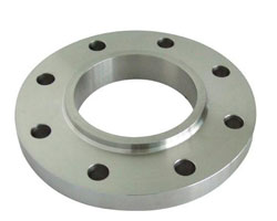
Slip On Flanges
Slip-on Flanges have bored with a diameter slightly larger than the pipe; this helps it to slide\slip over the pipe. This ANSI B16.5 SORF Flange is then welded inside and outside too, with fillet welding. Alloy Steel Slip On Plate Flanges are thinner compared to other ranges, cost-effective and are easy to use in fabricated applications.
| Dimensions: | ANSI B16.5, ANSI B16.47 Series A & B, MSS SP44, ASA, API-605, AWWA, Custom Drawings |
| Size: | 1/2″ (15 NB) to 48″ (1200NB) |
| Class: | 150 LBS, 300 LBS, 600 LBS, 900 LBS, 1500 LBS, 2500 LBS |
| BS: | BS4504 , BS4504, BS1560, BS10 , PN6 , PN10 , PN16 , PN25 , PN40, etc |
| Table: | D / E / F / H / J / K |
| Api Standards: | PSI-2000/3000/5000/10000/etc |
| JIS Standards: | 2220-2004 5k/10k/16k, etc |
| Flange Face Type: | Flate Face (FF), Raised Face (RF), Ring Type Joint (RTJ) |

BLRF Flanges
BLRF stands for Blind Flange Raised Face, which is a type of flange used to seal the end of a pipeline. Here’s a detailed overview of BLRF flanges:
| Property | Blind Flange Raised Face (BLRF) Flanges |
|---|---|
| Description | Flanges used to close the end of a pipe, with a raised face for better sealing. |
| Design | Features a solid, flat disc with a raised face that provides a surface for the gasket. |
| Flange Faces | Raised face, which ensures a tight seal by making full contact with the gasket. |
| Material Options | Available in various materials such as carbon steel, stainless steel, and alloy steels. |
| Pressure Rating | Available in various pressure ratings, including ANSI Class 150, 300, 600, etc. |
| Temperature Range | Varies depending on the material; generally used for moderate to high temperatures. |
| Common Applications | Used in applications where a pipe needs to be closed off, including in water, oil, gas, and chemical processing systems. |
| Advantages | Provides a secure closure for pipes; allows for easy removal if needed; offers a robust seal. |
| Disadvantages | Not suitable for applications where regular access to the pipe is required; can be bulky and heavy. |
| Installation | The flange is bolted to the pipe’s end and is sealed with a gasket to ensure no leakage. |
| Common Standards | ANSI B16.5, API 605, and other relevant industry standards. |
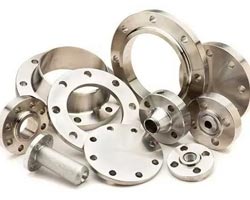
SS & MS Flanges
Stainless Steel (SS) and Mild Steel (MS) flanges are essential components in piping systems, used to connect pipes, valves, and other equipment. They come in various types and specifications based on the material and application.
| Property | Stainless Steel (SS) Flanges | Mild Steel (MS) Flanges |
|---|---|---|
| Material Composition | Stainless steel alloys (304, 316, etc.) | Mild steel (carbon steel) |
| Corrosion Resistance | High; resistant to rust and chemicals | Low; prone to rust and corrosion |
| Strength | High tensile strength and durability | Adequate strength; less durable |
| Temperature Range | Up to 870°C (1600°F) | Up to around 400°C (750°F) |
| Cost | Higher; due to material and processing | Lower; more cost-effective |
| Common Applications | Chemical, food processing, aerospace | Water supply, construction, automotive |
| Maintenance | Low; does not require frequent painting | Higher; may require regular maintenance |

SORF Flanges
SORF stands for Slip-On Raised Face flanges, which are a type of flange commonly used in piping systems. Here’s a detailed overview of SORF flanges in table format:
| Property | Slip-On Raised Face (SORF) Flanges |
|---|---|
| Description | Flanges that slide over the pipe and are then welded in place, with a raised face for sealing. |
| Design | The flange has a raised face that helps in forming a better seal with the gasket. |
| Flange Faces | Raised face, which helps to improve the sealing capability by providing a flat surface that contacts the gasket. |
| Material Options | Available in various materials including carbon steel, stainless steel, and alloy steels. |
| Pressure Rating | Typically available in various pressure ratings, such as ANSI Class 150, 300, 600, etc. |
| Temperature Range | Varies depending on material; generally suitable for moderate to high temperatures. |
| Common Applications | Used in a wide range of applications including water, oil, gas, and chemical processing systems. |
| Advantages | Easier to align and weld compared to other flange types; cost-effective; simple design. |
| Disadvantages | Less strength compared to Weld Neck flanges in high-pressure or high-stress applications. |
| Installation | Pipe is inserted into the flange, and then it is welded both inside and outside the flange to ensure a secure connection. |
| Common Standards | ANSI B16.5, API 605, and other relevant industry standards. |
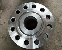
Ring Joint Flange
Ring Joint Flanges (RJF) are a specific type of flange used primarily for high-pressure and high-temperature applications. They are designed to provide a secure, leak-proof connection and are commonly used in industries such as oil and gas, petrochemical, and chemical processing. Here’s a detailed overview of Ring Joint Flanges:
| Property | Ring Joint Flanges (RJF) |
|---|---|
| Description | Flanges designed with a groove to accommodate a ring joint gasket, providing a high-pressure seal. |
| Design | Features a groove for a ring joint gasket, which is inserted between the flange faces to ensure a tight seal. |
| Flange Faces | Can have various face types, including Raised Face, Flat Face, or Ring Type Joint (RTJ). |
| Material Options | Typically made from carbon steel, stainless steel, and alloy steels. |
| Pressure Rating | Available in high pressure ratings, including ANSI Class 300, 600, 900, 1500, 2500, and higher. |
| Temperature Range | Suitable for high-temperature applications; temperature range depends on the material and gasket used. |
| Common Applications | Used in high-pressure and high-temperature applications such as oil and gas pipelines, refineries, and petrochemical facilities. |
| Advantages | Provides a very high level of sealing capability; suitable for extreme conditions; can handle high pressures and temperatures. |
| Disadvantages | Typically more expensive than other types of flanges; installation requires precision and care to ensure proper sealing. |
| Installation | The ring joint gasket is placed in the groove of the flange, and the flanges are bolted together. Proper alignment and torqueing are essential for a leak-proof seal. |
| Common Standards | API 6A, ASME B16.5, ASME B16.47, and other relevant industry standards. |
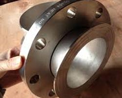
Lap Joint Flange
Lap Joint Flanges are a type of flange that consists of two parts: a stub end and a loose flange. This design is particularly useful for applications where frequent disassembly or alignment adjustments are necessary. Here's a detailed overview of Lap Joint Flanges:
| Property | Lap Joint Flanges |
|---|---|
| Description | Consists of a stub end and a loose flange; the stub end is welded to the pipe and the loose flange bolts onto it. |
| Design | The stub end is welded to the pipe and has a flange with a flat face, while the loose flange bolts onto the stub end, allowing for easy alignment and disassembly. |
| Flange Faces | Can be flat face, raised face, or ring type joint, depending on the application and requirements. |
| Material Options | Available in various materials such as carbon steel, stainless steel, and alloy steels. |
| Pressure Rating | Typically available in various pressure ratings, including ANSI Class 150, 300, 600, etc. |
| Temperature Range | Suitable for moderate to high-temperature applications, depending on material. |
| Common Applications | Used in applications where frequent disassembly is required, such as in piping systems, chemical processing, and shipbuilding. |
| Advantages | Allows for easy alignment and removal; reduces the need for precise welding and alignment; cost-effective compared to other flange types. |
| Disadvantages | Less suitable for high-pressure applications compared to other flange types like weld neck flanges; may require a gasket to ensure a leak-proof seal. |
| Installation | The stub end is welded to the pipe, and the loose flange is bolted onto the stub end. Proper alignment and gasket selection are necessary for a secure seal. |
| Common Standards | ANSI B16.5, ASME B16.47, and other relevant industry standards. |
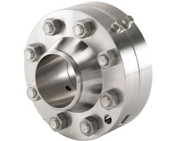
Oriface Flange
Orifice Flanges are specialized flanges used in piping systems to accommodate orifice plates, which measure the flow rate of fluids through a pipe. These flanges are designed to provide a secure and standardized way to install and remove orifice plates, which are critical for flow measurement and control. Here’s a detailed overview of Orifice Flanges
| Property | Orifice Flanges |
|---|---|
| Description | Flanges specifically designed to hold orifice plates for measuring fluid flow through a pipe. They include a special arrangement to support the orifice plate and ensure accurate flow measurement. |
| Design | Typically includes a raised face or ring joint face to accommodate the orifice plate, with bolt holes for securing the flange to the pipe. |
| Flange Faces | Can have raised face, ring type joint (RTJ), or flat face, depending on the application and requirements. |
| Material Options | Available in various materials such as carbon steel, stainless steel, and alloy steels. |
| Pressure Rating | Available in various pressure ratings, including ANSI Class 150, 300, 600, etc. |
| Temperature Range | Suitable for moderate to high temperatures, depending on the material and design. |
| Common Applications | Used in flow measurement applications in industries such as oil and gas, chemical processing, and water treatment. |
| Advantages | Provides a standardized method for flow measurement; allows for easy installation and removal of orifice plates; ensures accurate flow measurement. |
| Disadvantages | Typically requires precise alignment and installation; may be more complex than standard flanges due to the additional components. |
| Installation | The orifice plate is placed between the orifice flanges, which are then bolted together with gaskets to ensure a secure and leak-proof connection. Proper alignment and torqueing are crucial for accurate measurements. |
| Common Standards | ANSI B16.36, API 605, and other relevant industry standards for orifice flanges. |

Spectacles Flange
Spectacle Flanges are a type of flange used primarily for isolating sections of piping systems. They are designed to allow for easy maintenance, inspection, or modification of a pipeline by providing a way to block or open a line as needed. Here’s a detailed overview of Spectacle Flanges:
| Property | Spectacle Flanges |
|---|---|
| Description | Spectacle flanges consist of two connected flanges—one with a solid disc (the "blind" part) and one with a hole (the "spacer" part)—allowing for isolation or connection of the pipeline. |
| Design | The design includes two flanges joined by a solid plate (the "spectacle") that acts as a blind flange and a ring that acts as a spacer. This design allows for quick isolation or re-connection of sections of the pipeline. |
| Flange Faces | Can have various face types, including raised face, flat face, or ring type joint (RTJ), depending on the application and requirements. |
| Material Options | Available in various materials such as carbon steel, stainless steel, and alloy steels. |
| Pressure Rating | Available in various pressure ratings, including ANSI Class 150, 300, 600, etc. |
| Temperature Range | Suitable for a range of temperatures depending on material, generally up to moderate to high temperatures. |
| Common Applications | Used in pipelines where periodic isolation or inspection is required, such as in water, oil, gas, and chemical processing systems. |
| Advantages | Allows for easy isolation and re-connection of sections of piping; reduces the need for additional equipment or components; simplifies maintenance and inspection processes. |
| Disadvantages | Typically requires careful alignment and installation; can be more bulky compared to other flange types. |
| Installation | The spectacle flange is installed between two flanges on the pipeline. The solid disc is positioned to block flow, while the ring can be used to connect the line when needed. Proper alignment and bolting are essential to ensure a secure and leak-proof seal. |
| Common Standards | ANSI B16.5, ASME B16.47, and other relevant industry standards. |
